1. Networking Basics & Cabling
What Is a Network?
A network is a collection of interconnected devices (computers, servers, printers, phones) that communicate and share resources. At its core, networking enables:
- File sharing — Centralized storage and collaborative access to documents.
- Printer sharing — Multiple users can print to a single device.
- Internet access — Shared gateway for web connectivity.
- Centralized management — A Domain Controller (e.g., Windows Active Directory) authenticates users, enforces group policies, and manages permissions across the entire network.
Key Term — Domain Controller: A server that responds to authentication requests and verifies users on a network. It acts as the “gatekeeper” for all network resources.
Cabling Types
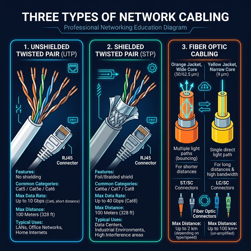
UTP (Unshielded Twisted Pair)
| Property | Details |
|---|---|
| Medium | Copper wires twisted in pairs |
| Connector | RJ45 (8-pin modular) |
| Max Segment Length | 100 meters (328 ft) — often cited as 120m with patch cables |
| Shielding | None (vulnerable to EMI in noisy environments) |
| Use Case | LAN connections, office wiring, desktop-to-switch links |
UTP Limitation: Because there is no shielding, UTP cables are susceptible to electromagnetic interference (EMI) and crosstalk. In environments with heavy electrical equipment (factories, hospitals), STP or fiber should be used instead.
STP (Shielded Twisted Pair)
| Property | Details |
|---|---|
| Medium | Copper wires twisted in pairs, wrapped in metallic foil or braided shield |
| Connector | RJ45 (8-pin modular), sometimes with grounding drain wire |
| Max Segment Length | 100 meters (328 ft) |
| Shielding | Foil (FTP), Braided (STP), or Both (S/FTP) — provides EMI protection |
| Use Case | Industrial environments, data centers, hospitals, areas with high EMI |
Shielding Variants:
| Abbreviation | Full Name | Shield Type | Best For |
|---|---|---|---|
| FTP | Foiled Twisted Pair | Overall foil around all pairs | General EMI protection |
| STP | Shielded Twisted Pair | Braided shield around each pair | High-interference environments |
| S/FTP | Screened Foiled Twisted Pair | Overall braid + individual foil per pair | Maximum protection (data centers) |
| S/STP | Screened Shielded Twisted Pair | Overall braid + individual braid per pair | Extreme interference zones |
STP vs UTP: STP provides superior protection against EMI and crosstalk, but it is more expensive, thicker, less flexible, and requires proper grounding to be effective. If the shield is not grounded, it can actually worsen interference by acting as an antenna.
UTP vs STP Comparison:
| Feature | UTP | STP |
|---|---|---|
| Cost | Lower | Higher |
| Flexibility | More flexible, easier to install | Stiffer, harder to route |
| EMI Protection | None | Excellent (when properly grounded) |
| Weight | Lighter | Heavier |
| Grounding | Not required | Required for shield effectiveness |
| Common Categories | Cat5, Cat5e, Cat6 | Cat6a, Cat7, Cat8 |
| Typical Environment | Office, home | Data center, industrial, medical |
Category Breakdown (UTP & STP):
| Category | Max Speed | Max Bandwidth | Shielding | Typical Use |
|---|---|---|---|---|
| Cat5 | 100 Mbps | 100 MHz | UTP | Legacy networks |
| Cat5e | 1 Gbps | 100 MHz | UTP | Most common office wiring |
| Cat6 | 10 Gbps (up to 55m) | 250 MHz | UTP or STP | High-performance LANs |
| Cat6a | 10 Gbps (full 100m) | 500 MHz | Usually STP | Data centers, PoE+ environments |
| Cat7 | 10 Gbps | 600 MHz | S/FTP (required) | Shielded, industrial use |
| Cat8 | 25/40 Gbps | 2000 MHz | S/FTP (required) | Short-run data center connections |
Wiring Standards: Two pinout standards exist — T568A and T568B. Use the same standard on both ends for a straight-through cable (device → switch). Use different standards for a crossover cable (device → device). Most modern switches support Auto-MDIX, automatically detecting the cable type.
Fiber Optic
| Property | Details |
|---|---|
| Medium | Glass or plastic core transmitting light pulses |
| Connectors | SC, LC, ST, MTP/MPO |
| Immunity | Completely immune to electromagnetic interference (EMI) |
| Security | Very difficult to tap without detection |
| Use Case | Backbone links, WAN connections, data centers |
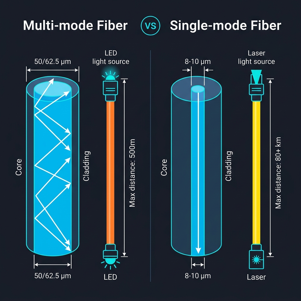
Multi-mode vs. Single-mode:
| Feature | Multi-mode (MMF) | Single-mode (SMF) |
|---|---|---|
| Core Diameter | 50 or 62.5 µm | 8–10 µm |
| Light Source | LED or VCSEL | Laser |
| Max Distance | ~500 m (OM3/OM4 can reach 300–550m at 10G) | Up to 80+ km |
| Cost | Lower (cheaper transceivers) | Higher (precision laser) |
| Best For | Campus/building backbones | Long-haul ISP, metro, WAN links |
| Cable Color | Orange (OM1/OM2) or Aqua (OM3/OM4) | Yellow |
2. Network Devices
Routers
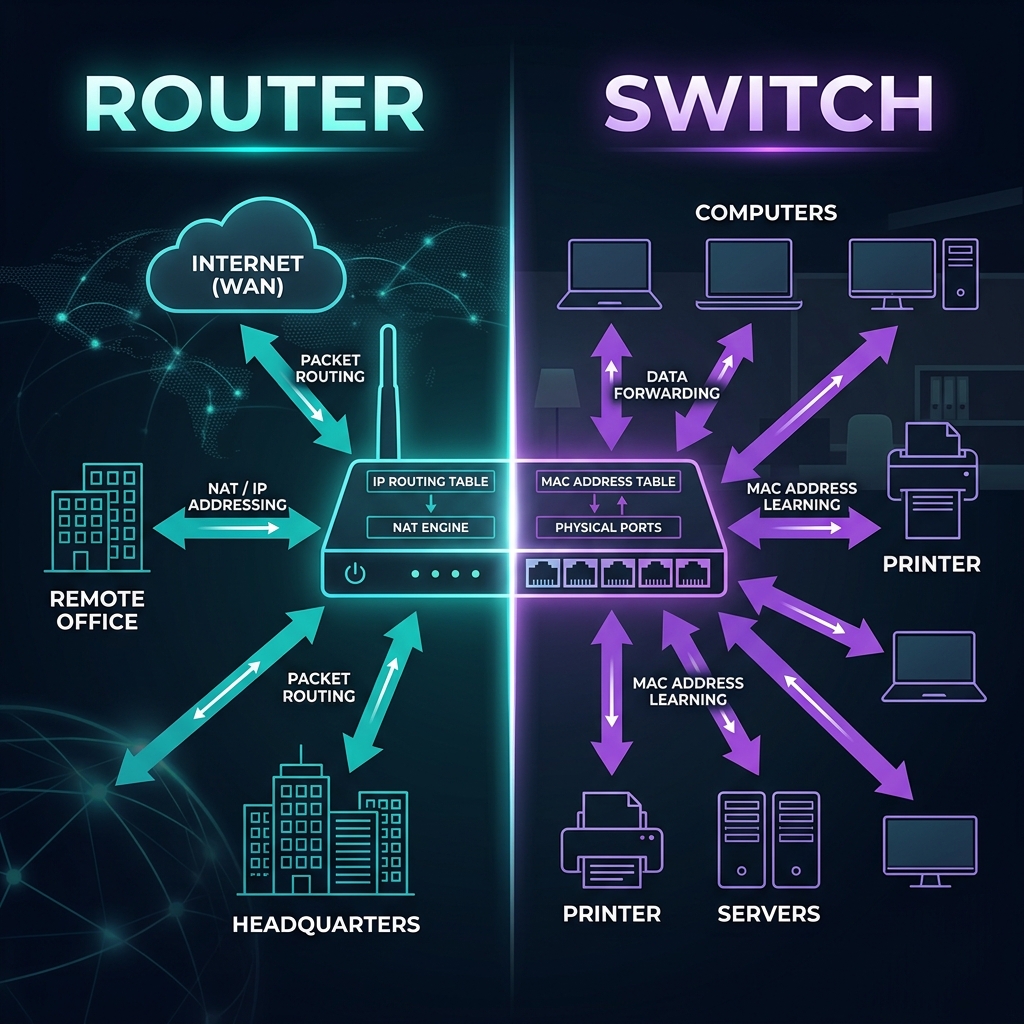
A router operates at Layer 3 (Network Layer) of the OSI model and is responsible for forwarding packets between different networks.
| Aspect | Details |
|---|---|
| Primary Function | Interconnect separate networks; route packets based on IP addresses |
| OSI Layer | Layer 3 (Network) |
| Addressing | Uses IP addresses to make forwarding decisions |
| Broadcast Domain | Each interface is a separate broadcast domain |
| Key Use Cases | WAN connectivity, internet access, inter-VLAN routing, VPN termination |
| Intelligence | Maintains a routing table with best paths to destination networks |
How Routing Works:
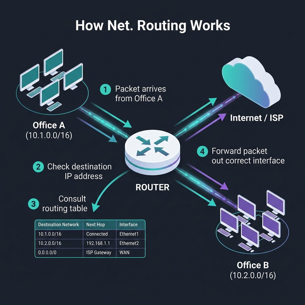
- A packet arrives at the router.
- The router examines the destination IP address.
- It consults the routing table for the best matching route.
- The packet is forwarded out the appropriate interface.
Switches
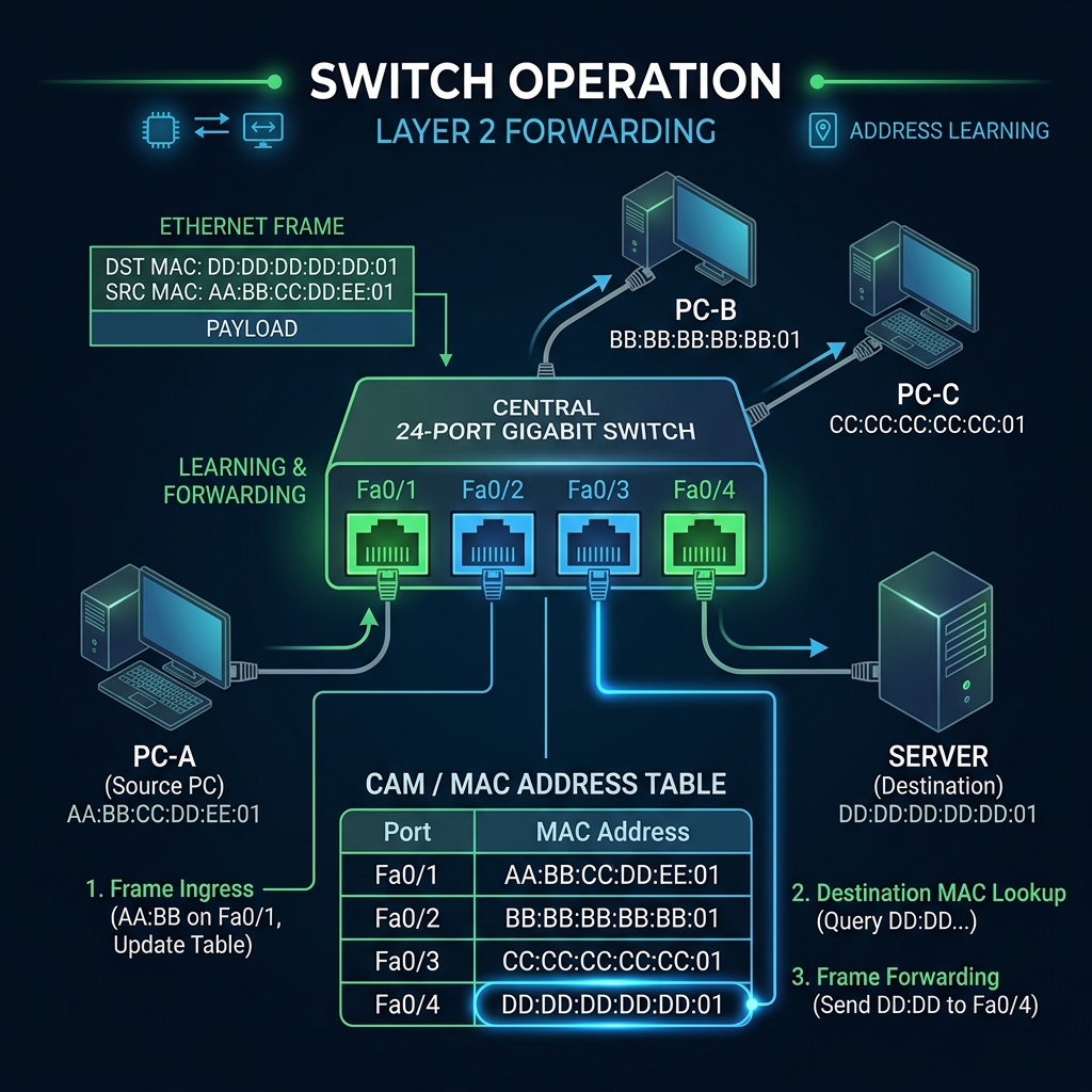
A switch operates at Layer 2 (Data Link Layer) and connects devices within the same network (LAN).
| Aspect | Details |
|---|---|
| Primary Function | Forward frames within a LAN based on MAC addresses |
| OSI Layer | Layer 2 (Data Link) — Layer 3 switches also exist |
| Addressing | Uses MAC addresses (stored in a MAC address table / CAM table) |
| Broadcast Domain | All ports share one broadcast domain (unless VLANs are configured) |
| Collision Domain | Each port is its own collision domain (full duplex) |
| Key Use Cases | Connecting PCs, servers, printers, IP phones, access points |
How Switching Works:
Quick Comparison
| Feature | Router | Switch |
|---|---|---|
| OSI Layer | Layer 3 | Layer 2 (or Layer 3) |
| Addressing | IP Address | MAC Address |
| Broadcast Domains | Separates them | Single domain (per VLAN) |
| Primary Use | WAN / Inter-network | LAN / Intra-network |
| Table Used | Routing Table | MAC / CAM Table |
3. IP Addressing & Subnetting
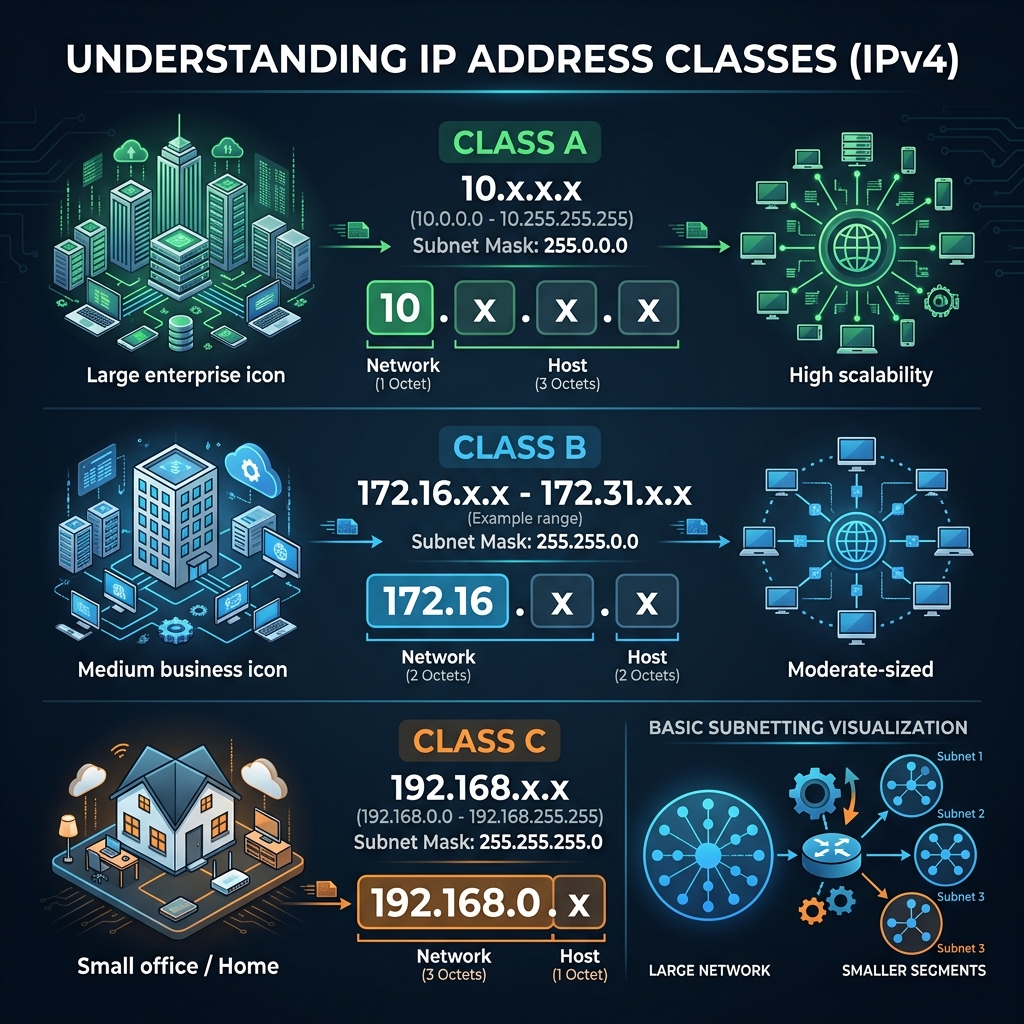
IP Address Fundamentals
An IP address (IPv4) is a 32-bit number divided into four octets, each ranging from 0 to 255. It serves as a unique logical identifier for every device on a network.
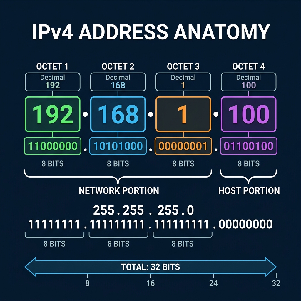
Every IP address has two components:
- Network Portion — Identifies which network the host belongs to.
- Host Portion — Identifies the specific device on that network.
The subnet mask determines where the split occurs.
IP Address Classes (Classful Addressing)
| Class | First Octet Range | Default Subnet Mask | Network / Host | Private Range | Max Hosts |
|---|---|---|---|---|---|
| A | 1–126 | 255.0.0.0 (/8) | N.H.H.H | 10.0.0.0 – 10.255.255.255 |
~16.7 million |
| B | 128–191 | 255.255.0.0 (/16) | N.N.H.H | 172.16.0.0 – 172.31.255.255 |
~65,000 |
| C | 192–223 | 255.255.255.0 (/24) | N.N.N.H | 192.168.0.0 – 192.168.255.255 |
254 |
| D | 224–239 | N/A | Multicast | — | — |
| E | 240–255 | N/A | Experimental | — | — |
127.0.0.0/8 is reserved for loopback (localhost) testing — e.g.,
127.0.0.1.
Subnetting — Dividing Networks
Subnetting is the practice of borrowing bits from the host portion of an IP address to create additional sub-networks. This provides:
- Efficient IP usage — No wasted addresses.
- Reduced broadcast traffic — Smaller broadcast domains.
- Improved security — Segments can be isolated with ACLs.
- Simplified management — Logical grouping by department, floor, or function.
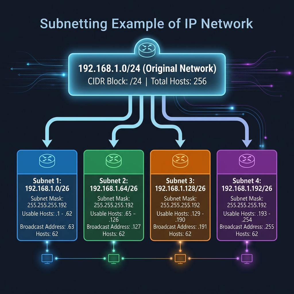
Subnetting Cheat Table (Class C — /24 base):
| CIDR | Subnet Mask | # Subnets | # Usable Hosts | Block Size |
|---|---|---|---|---|
| /25 | 255.255.255.128 | 2 | 126 | 128 |
| /26 | 255.255.255.192 | 4 | 62 | 64 |
| /27 | 255.255.255.224 | 8 | 30 | 32 |
| /28 | 255.255.255.240 | 16 | 14 | 16 |
| /29 | 255.255.255.248 | 32 | 6 | 8 |
| /30 | 255.255.255.252 | 64 | 2 | 4 |
Formula: Usable Hosts = 2^(host bits) − 2 (subtract network & broadcast addresses)
Subnetting Example:
Special Addresses
| Address | Purpose |
|---|---|
0.0.0.0 |
Default route / “any network” |
127.0.0.1 |
Loopback (localhost) |
169.254.x.x |
APIPA (auto-assigned when DHCP fails) |
255.255.255.255 |
Limited broadcast (current network) |
x.x.x.0 |
Network address (first in subnet) |
x.x.x.255 |
Broadcast address (last in subnet, for /24) |
4. The OSI Model
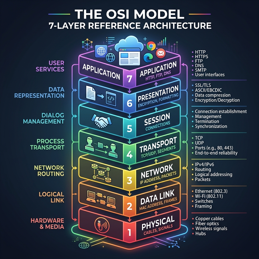
The Open Systems Interconnection (OSI) model is a conceptual framework standardized by the ISO that divides network communication into 7 abstraction layers. Each layer serves the layer above it and is served by the layer below it.
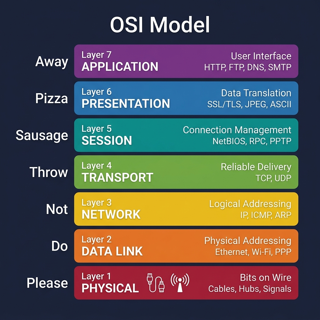
Complete Layer Breakdown
Mnemonic (Bottom → Top): “Please Do Not Throw Sausage Pizza Away” Mnemonic (Top → Bottom): “All People Seem To Need Data Processing”
Detailed Layer Descriptions
Layer 1 — Physical
| Attribute | Details |
|---|---|
| PDU | Bits |
| Function | Transmits raw binary data (0s and 1s) over a physical medium |
| Devices | Cables (UTP, STP, Fiber), Hubs, Repeaters, Connectors |
| Key Concepts | Voltage levels, pin layouts, data rates, physical topologies (star, mesh, bus) |
| Concerns | Signal attenuation, interference, cable standards |
Layer 2 — Data Link
| Attribute | Details |
|---|---|
| PDU | Frames |
| Function | Provides node-to-node data transfer, error detection, and MAC addressing |
| Sub-layers | LLC (Logical Link Control) and MAC (Media Access Control) |
| Devices | Switches, Bridges, NICs |
| Key Concepts | MAC addresses (48-bit, e.g., AA:BB:CC:DD:EE:FF), ARP, frame check sequence (FCS), VLANs |
| Concerns | Collision detection (CSMA/CD), broadcast storms, STP |
Layer 3 — Network
| Attribute | Details |
|---|---|
| PDU | Packets |
| Function | Logical addressing (IP) and routing packets across networks |
| Devices | Routers, Layer 3 Switches |
| Protocols | IPv4, IPv6, ICMP, OSPF, EIGRP, BGP |
| Key Concepts | IP addressing, subnetting, routing tables, TTL, fragmentation |
| Concerns | Routing loops, black holes, MTU mismatches |
Layer 4 — Transport
| Attribute | Details |
|---|---|
| PDU | Segments (TCP) / Datagrams (UDP) |
| Function | End-to-end data delivery, segmentation, flow control, error recovery |
| Protocols | TCP (reliable, connection-oriented) and UDP (fast, connectionless) |
| Key Concepts | Port numbers, three-way handshake (SYN → SYN-ACK → ACK), windowing, checksums |
TCP vs UDP:
| Feature | TCP | UDP |
|---|---|---|
| Connection | Connection-oriented | Connectionless |
| Reliability | Guaranteed delivery | Best-effort |
| Ordering | Maintains order | No ordering |
| Speed | Slower (overhead) | Faster (minimal overhead) |
| Use Cases | Web (HTTP), Email (SMTP), File Transfer (FTP) | Streaming, DNS, VoIP, Gaming |
Layer 5 — Session
| Attribute | Details |
|---|---|
| PDU | Data |
| Function | Establishes, manages, and terminates sessions between applications |
| Protocols | NetBIOS, RPC, PPTP, SCP |
| Key Concepts | Session checkpoints, dialog control (simplex, half-duplex, full-duplex), session restoration |
Layer 6 — Presentation
| Attribute | Details |
|---|---|
| PDU | Data |
| Function | Translates data between the application and network formats |
| Responsibilities | Encryption/Decryption (SSL/TLS), Compression, Character encoding (ASCII, Unicode), Serialization (JSON, XML) |
| Key Concepts | Data format standardization, MIME types, image formats (JPEG, PNG, GIF) |
Layer 7 — Application
| Attribute | Details |
|---|---|
| PDU | Data |
| Function | Provides network services directly to the end-user’s applications |
| Protocols | HTTP/HTTPS (web), FTP/SFTP (file transfer), SMTP/IMAP/POP3 (email), DNS (name resolution), DHCP (dynamic IP), SSH (secure shell), SNMP (monitoring), Telnet |
| Key Concepts | User authentication, API communication, web browsing, email clients |
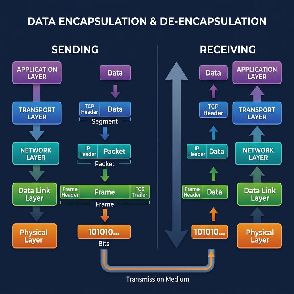
Data Encapsulation Flow
5. The TCP/IP Model
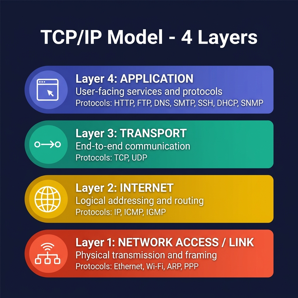
The TCP/IP Model (also called the Internet Protocol Suite or DoD Model) is the practical, real-world networking model that powers the modern internet. Unlike the OSI model’s 7 theoretical layers, TCP/IP consolidates functionality into 4 streamlined layers that map directly to how protocols are actually implemented.
Why TCP/IP matters: While the OSI model is excellent for learning and troubleshooting, the TCP/IP model is what the internet actually runs on. Every device connected to the internet uses the TCP/IP protocol stack.
TCP/IP Layer Breakdown
Layer 1 — Network Access (Link)
| Attribute | Details |
|---|---|
| OSI Equivalent | Physical + Data Link (Layers 1 & 2) |
| PDU | Frames / Bits |
| Function | Handles physical transmission, hardware addressing (MAC), and framing |
| Protocols | Ethernet (802.3), Wi-Fi (802.11), ARP, PPP, Frame Relay, HDLC |
| Devices | NICs, Switches, Hubs, Cables, Access Points |
| Key Concepts | MAC addressing, media access control, physical signaling, frame encapsulation |
This layer combines the OSI’s Physical and Data Link layers because TCP/IP treats them as a single concern — getting bits from one node to the directly connected next node.
Layer 2 — Internet
| Attribute | Details |
|---|---|
| OSI Equivalent | Network (Layer 3) |
| PDU | Packets |
| Function | Logical addressing, routing, and packet forwarding across networks |
| Protocols | IPv4, IPv6, ICMP, IGMP, IPsec |
| Devices | Routers, Layer 3 Switches |
| Key Concepts | IP addressing, subnetting, routing, TTL, fragmentation, NAT |
Key Protocols at this Layer:
| Protocol | Purpose | Details |
|---|---|---|
| IPv4 | Primary addressing protocol | 32-bit addresses, 4.3 billion unique addresses |
| IPv6 | Next-gen addressing | 128-bit addresses, virtually unlimited address space |
| ICMP | Diagnostics & error reporting | Used by ping and traceroute commands |
| IGMP | Multicast group management | Allows hosts to join/leave multicast groups |
| IPsec | Security at the IP layer | Encryption & authentication for VPNs |
Layer 3 — Transport
| Attribute | Details |
|---|---|
| OSI Equivalent | Transport (Layer 4) |
| PDU | Segments (TCP) / Datagrams (UDP) |
| Function | End-to-end communication, reliability, flow control, multiplexing via port numbers |
| Protocols | TCP, UDP |
| Key Concepts | Port numbers, sockets, three-way handshake, flow control, congestion control |
TCP Three-Way Handshake:
| Step | Direction | Flag | Purpose |
|---|---|---|---|
| 1 | Client → Server | SYN | “I want to connect” (includes initial sequence number) |
| 2 | Server → Client | SYN-ACK | “Connection accepted” (acknowledges + sends own sequence number) |
| 3 | Client → Server | ACK | “Acknowledged” (connection established, data can flow) |
TCP vs UDP — When to Use Each:
| Scenario | Use TCP | Use UDP |
|---|---|---|
| Web browsing | HTTP/HTTPS needs reliability | |
| File transfer | FTP/SFTP — no data loss allowed | |
| SMTP/IMAP — must deliver complete messages | ||
| Live streaming | Speed over reliability | |
| Online gaming | Low latency critical | |
| DNS lookups | Small, fast queries | |
| VoIP calls | Real-time audio | |
| Video conferencing | Real-time video + audio |
Layer 4 — Application
| Attribute | Details |
|---|---|
| OSI Equivalent | Session + Presentation + Application (Layers 5, 6, 7) |
| PDU | Data |
| Function | Provides all user-facing services, session management, data formatting, and protocol-level communication |
| Protocols | HTTP/HTTPS, FTP, SSH, Telnet, SMTP, POP3, IMAP, DNS, DHCP, SNMP, NTP, LDAP, RDP |
| Key Concepts | Client-server model, APIs, authentication, web services, name resolution |
This layer merges the OSI’s Session, Presentation, and Application layers because in practice, most application protocols handle all three functions internally.
Common Application Layer Protocols:
| Protocol | Port(s) | Transport | Purpose |
|---|---|---|---|
| HTTP | 80 | TCP | Web page transfer (unencrypted) |
| HTTPS | 443 | TCP | Secure web page transfer (TLS encrypted) |
| FTP | 20, 21 | TCP | File transfer (data + control channels) |
| SSH | 22 | TCP | Secure remote shell access |
| Telnet | 23 | TCP | Remote shell access (unencrypted — avoid!) |
| SMTP | 25 | TCP | Sending email |
| DNS | 53 | TCP/UDP | Domain name → IP address resolution |
| DHCP | 67, 68 | UDP | Automatic IP address assignment |
| SNMP | 161, 162 | UDP | Network device monitoring & management |
| NTP | 123 | UDP | Time synchronization |
| LDAP | 389 | TCP | Directory services (Active Directory) |
| RDP | 3389 | TCP | Remote desktop access |
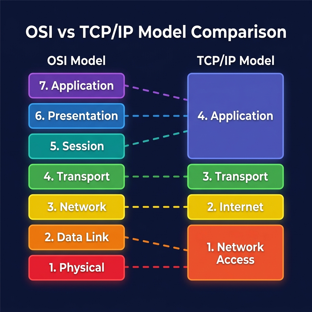
OSI vs TCP/IP — Side-by-Side Comparison
| Feature | OSI Model | TCP/IP Model |
|---|---|---|
| Full Name | Open Systems Interconnection | Internet Protocol Suite |
| Developed By | ISO (International Organization for Standardization) | DARPA / DoD (US Department of Defense) |
| Layers | 7 | 4 |
| Purpose | Theoretical reference model | Practical, implementation-based model |
| Approach | Protocol-independent framework | Built around TCP/IP protocols |
| Layer Mapping | Physical, Data Link, Network, Transport, Session, Presentation, Application | Network Access, Internet, Transport, Application |
| Real-World Use | Education, troubleshooting, certification exams | The actual internet runs on this |
| Session Management | Dedicated Session layer (L5) | Handled within Application layer |
| Encryption | Dedicated Presentation layer (L6) | Handled within Application layer (TLS/SSL) |
| Strictness | Strict layer separation | Layers can overlap |
Layer Mapping Between Models:
| OSI Layer(s) | TCP/IP Layer | Mapping Rationale |
|---|---|---|
| Layer 1 (Physical) + Layer 2 (Data Link) | Network Access | Both handle hardware-level communication |
| Layer 3 (Network) | Internet | Direct 1:1 mapping — IP addressing & routing |
| Layer 4 (Transport) | Transport | Direct 1:1 mapping — TCP/UDP |
| Layer 5 (Session) + Layer 6 (Presentation) + Layer 7 (Application) | Application | TCP/IP merges user-facing functionality |
TCP/IP Encapsulation
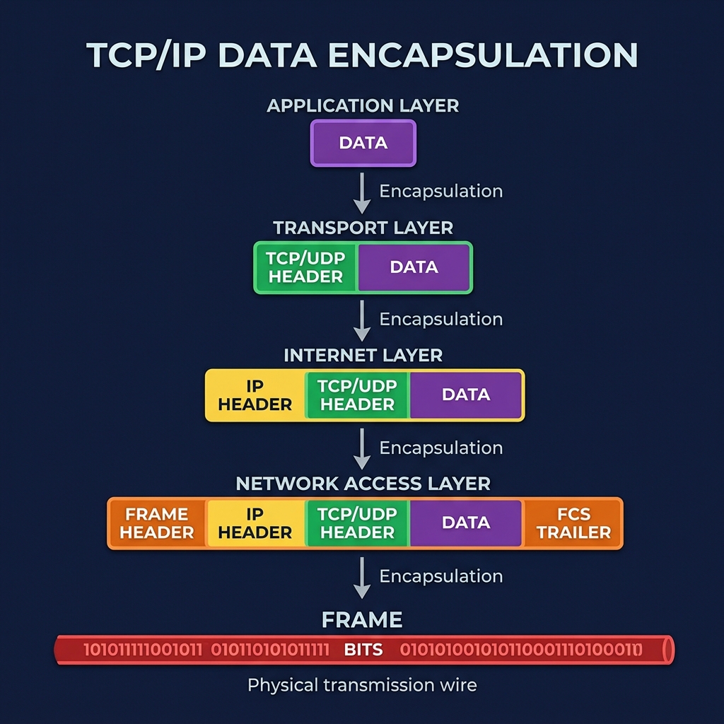
| Layer | Header Added | Resulting PDU | Example |
|---|---|---|---|
| Application | — | Data | HTTP request body |
| Transport | TCP/UDP Header (src port, dst port, seq#) | Segment / Datagram | Port 80 → Port 443 |
| Internet | IP Header (src IP, dst IP, TTL) | Packet | 192.168.1.10 → 8.8.8.8 |
| Network Access | Frame Header (src MAC, dst MAC) + FCS Trailer | Frame | AA:BB → CC:DD |
| Physical wire | — | Bits | Electrical / light signals |
6. Network Design & Security
Three-Tier Network Architecture
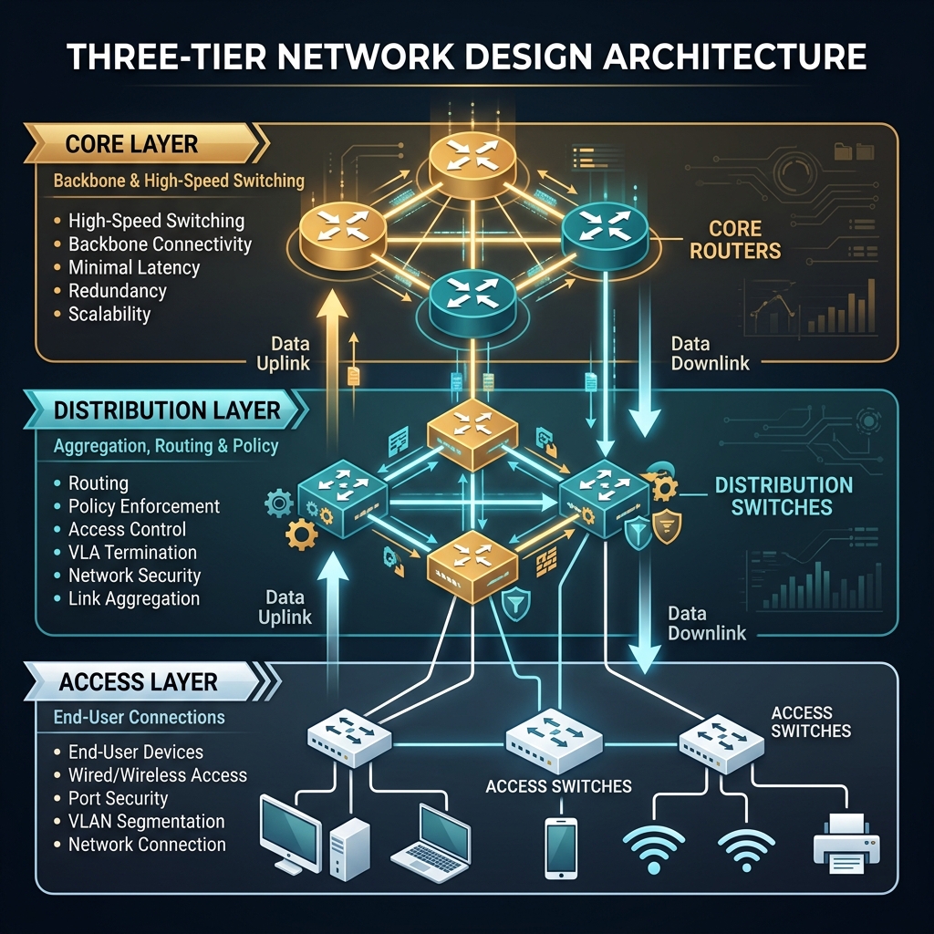
A well-designed enterprise network follows a hierarchical three-tier model that provides scalability, redundancy, and manageability.
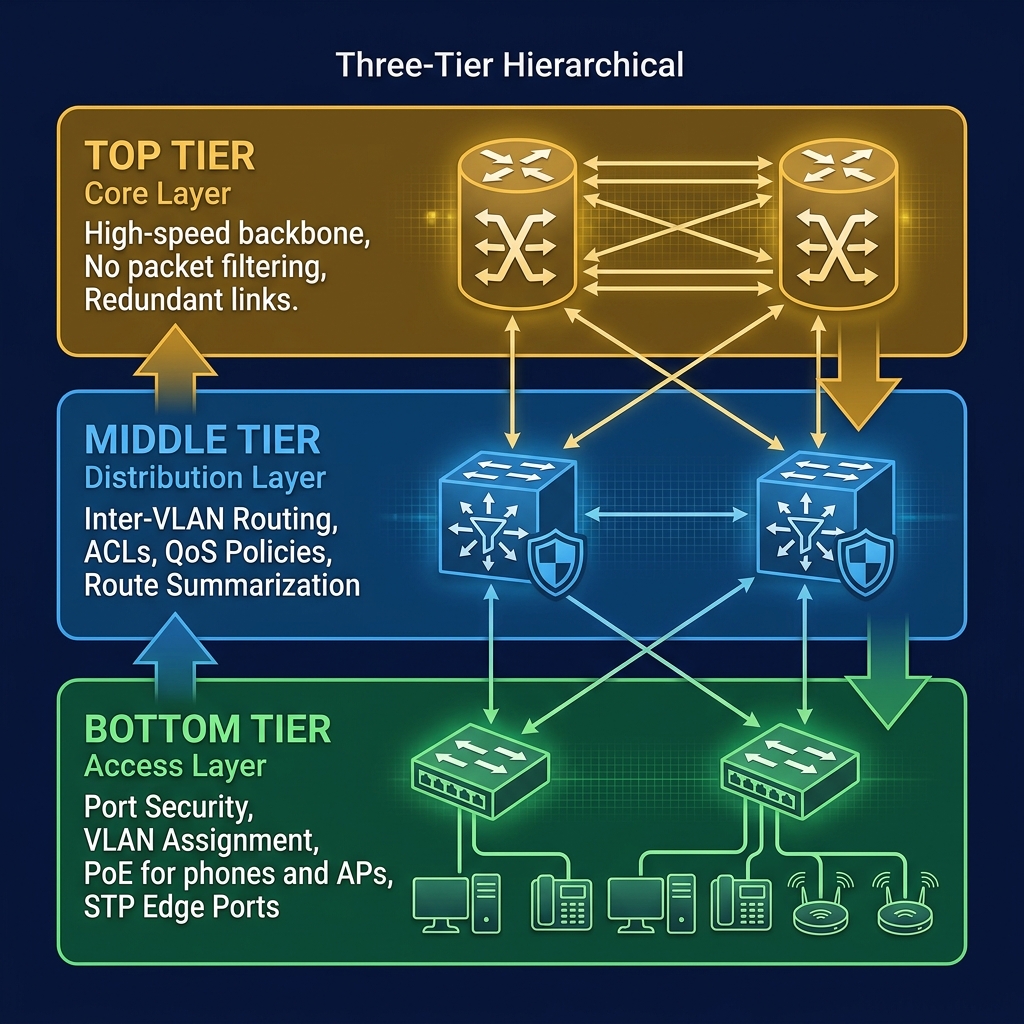
| Layer | Purpose | Typical Devices | Key Features |
|---|---|---|---|
| Core | High-speed backbone | High-end routers/switches | Speed, redundancy, no filtering |
| Distribution | Policy & routing | Layer 3 switches, firewalls | ACLs, route summarization, QoS |
| Access | User connectivity | Layer 2 switches, APs | Port security, VLANs, PoE |
Network Security
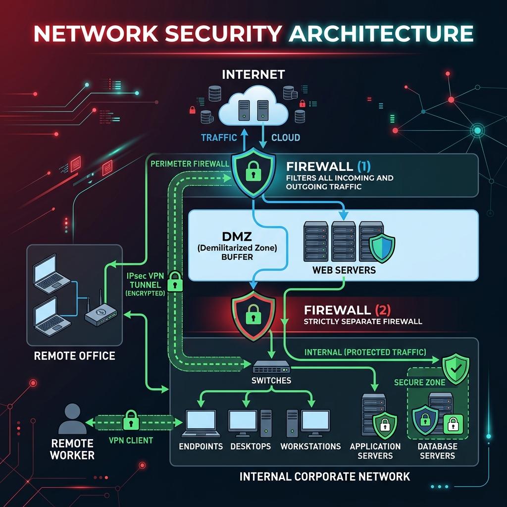
DMZ (Demilitarized Zone)
A DMZ is an isolated sub-network that sits between the internal trusted network and the external untrusted network (internet). It hosts public-facing services while protecting the internal network.
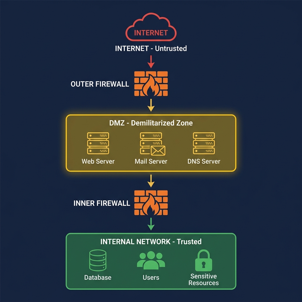
DMZ Best Practices:
- Only expose necessary services (HTTP/HTTPS, SMTP, DNS).
- Use dual firewalls (outer + inner) for defense in depth.
- DMZ servers should never directly access internal resources.
- Monitor and log all DMZ traffic.
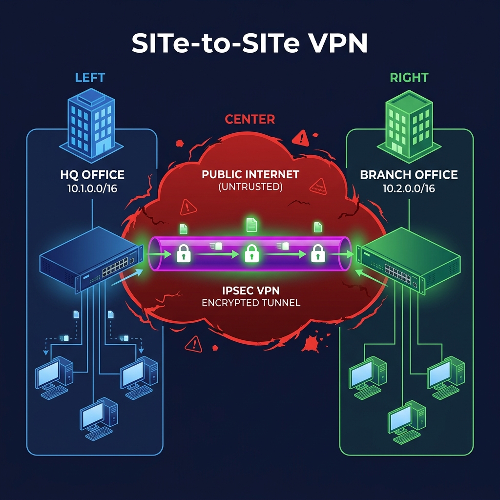
VPN (Virtual Private Network)
A VPN creates an encrypted tunnel over the public internet, allowing remote users or offices to securely access the internal network as if they were physically connected.
| VPN Type | Description | Protocol Examples |
|---|---|---|
| Site-to-Site | Connects two entire networks (e.g., HQ ↔ Branch Office) | IPsec, GRE over IPsec |
| Remote Access | Individual user connects to the corporate network | SSL/TLS VPN, IPsec client |
| DMVPN | Dynamic mesh VPN for multiple sites | mGRE + IPsec + NHRP |
Leased Lines
A leased line is a dedicated, private point-to-point connection between two locations, provided by a telecom carrier. Unlike VPNs, the traffic does not traverse the public internet.
| Feature | VPN | Leased Line |
|---|---|---|
| Medium | Public internet | Dedicated private link |
| Cost | Lower | Higher (monthly recurring) |
| Bandwidth | Variable (shared) | Guaranteed (SLA) |
| Security | Encrypted tunnel | Inherently private |
| Latency | Higher, variable | Low, consistent |
| Best For | Remote access, cost-sensitive | Mission-critical, low-latency needs |
7. Router & Switching Configuration
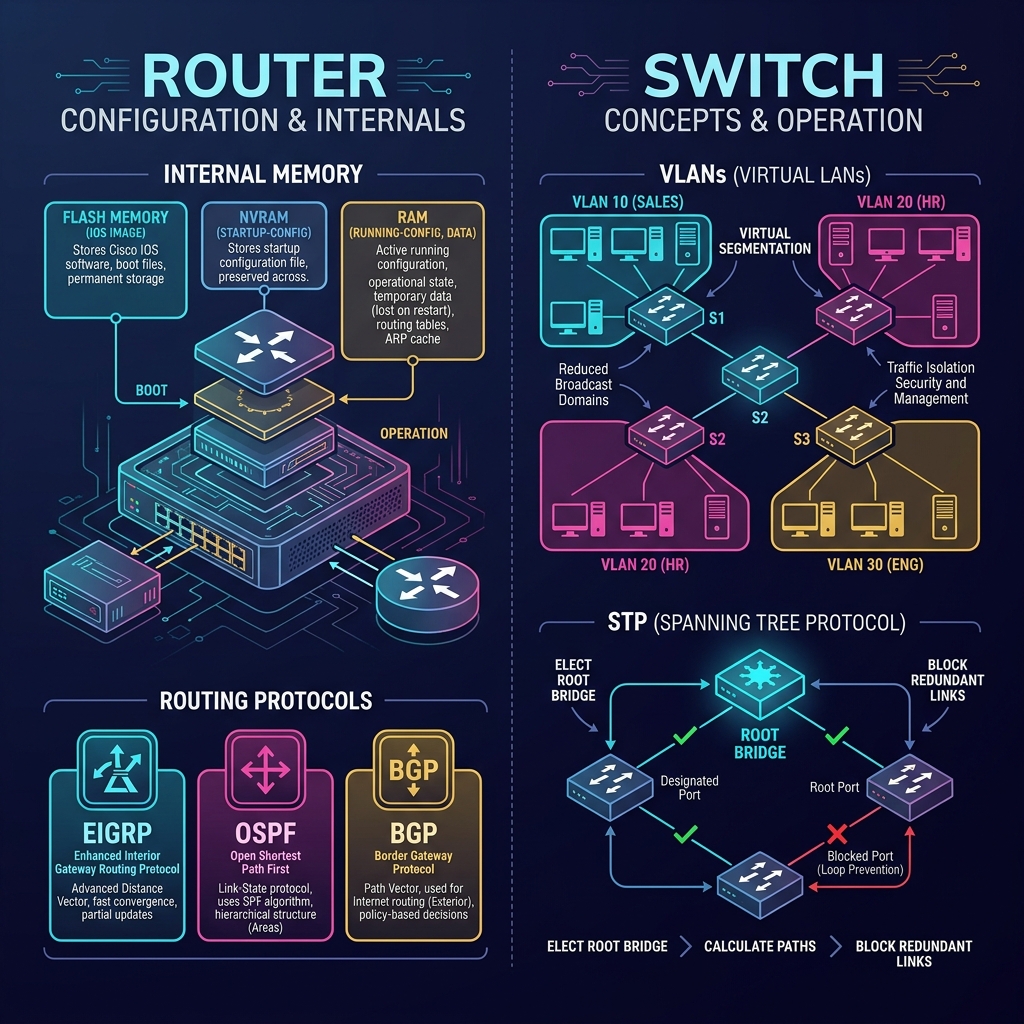
Router Internals — Memory Architecture
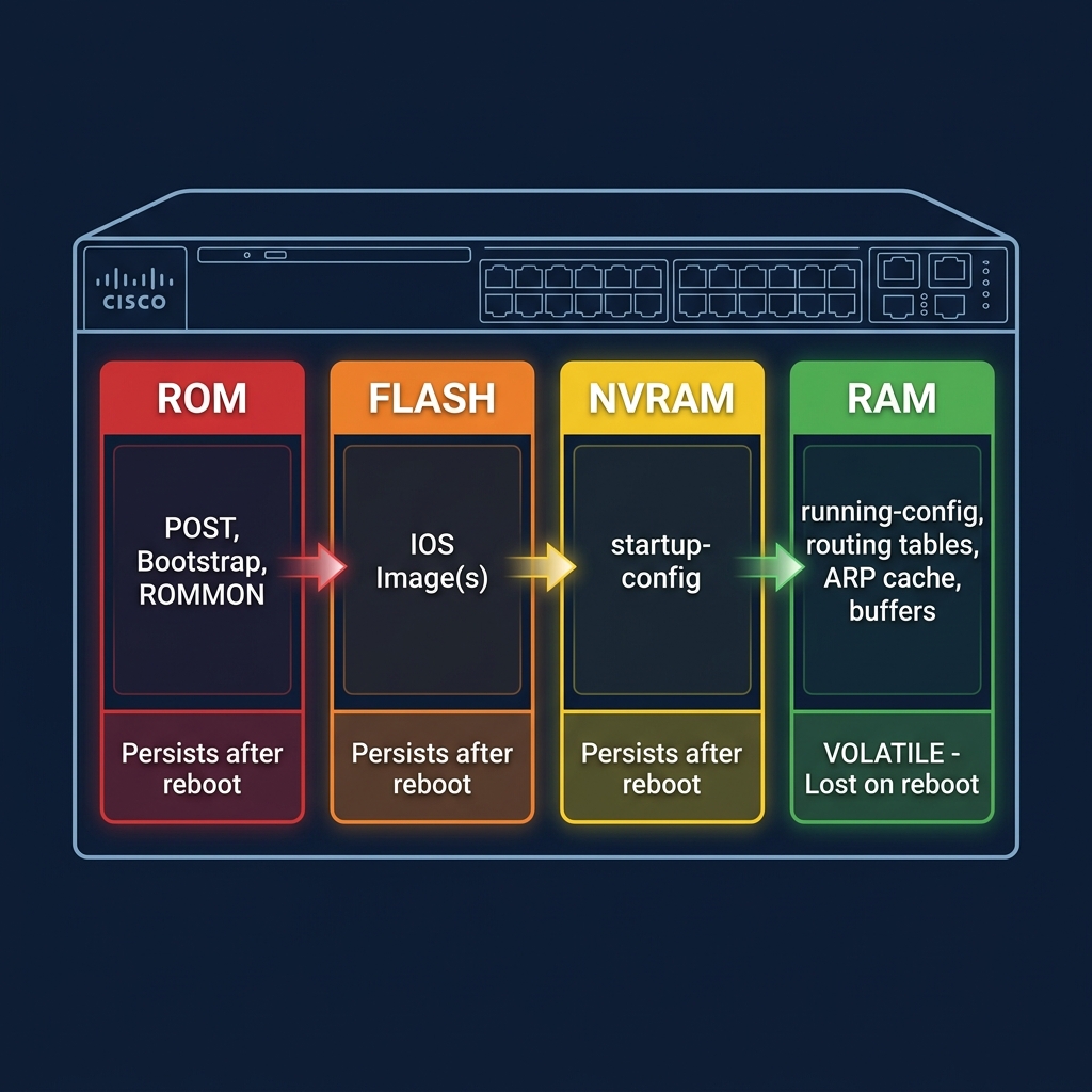
| Memory | Content | Persists after Reboot? | Notes |
|---|---|---|---|
| ROM | POST, Bootstrap, ROMMON | Yes | Read-only; hardware diagnostics |
| Flash | IOS operating system image(s) | Yes | Can hold multiple IOS versions |
| NVRAM | Startup configuration file | Yes | Loaded into RAM on boot |
| RAM | Running configuration, routing tables, ARP cache, buffers | No | Active working memory |
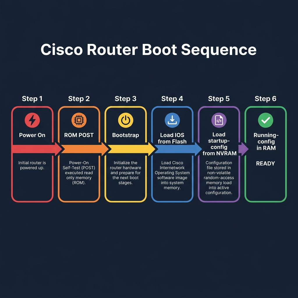
Boot Sequence:
Routing Protocols
Routing protocols determine how routers discover and share information about network paths.
EIGRP (Enhanced Interior Gateway Routing Protocol)
| Attribute | Details |
|---|---|
| Type | Advanced distance-vector (hybrid) |
| Standard | Cisco-proprietary (now partially open — RFC 7868) |
| Algorithm | DUAL (Diffusing Update Algorithm) |
| Metric | Composite: Bandwidth, Delay, Reliability, Load, MTU |
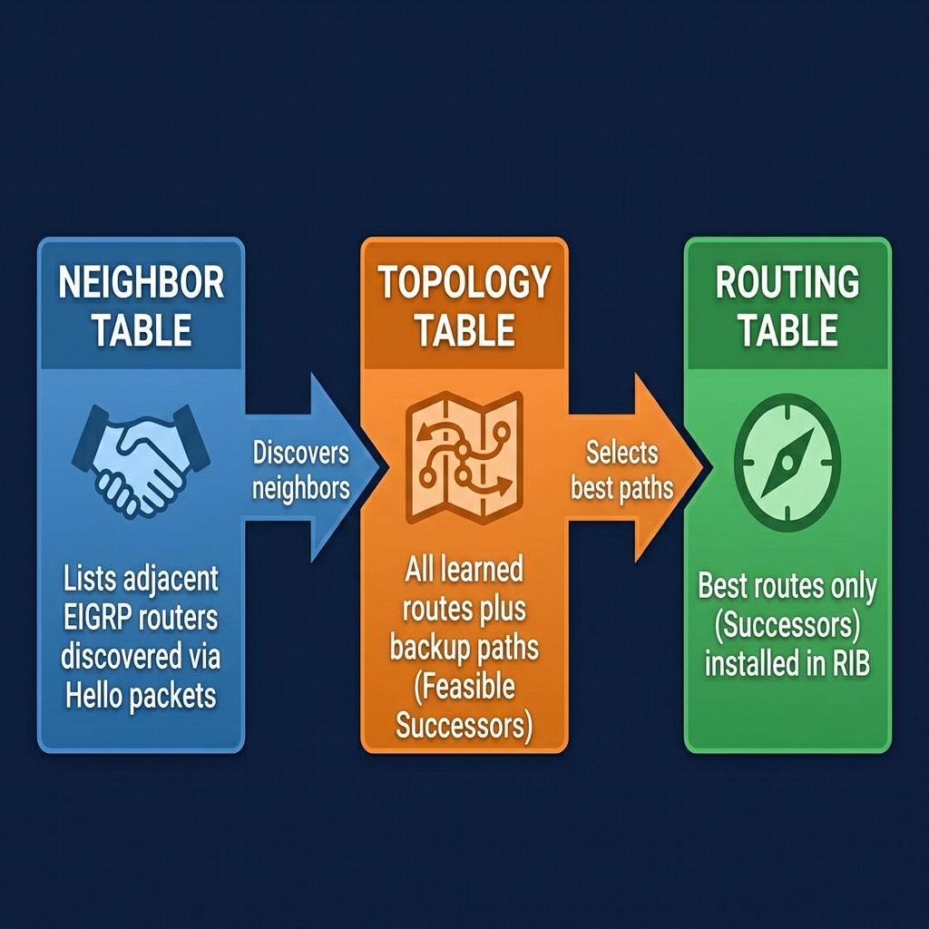
| Convergence | Very fast (maintains backup routes via Feasible Successors) |
| Admin Distance | 90 (internal), 170 (external) |
| Transport | IP Protocol 88 (not TCP or UDP) |
EIGRP Three Tables:
Basic EIGRP Configuration:
| Step | Command | Purpose |
|---|---|---|
| 1 | Router(config)# router eigrp 100 |
Enable EIGRP with AS number 100 |
| 2 | Router(config-router)# network 10.0.0.0 |
Advertise the 10.x.x.x network |
| 3 | Router(config-router)# network 192.168.1.0 0.0.0.255 |
Advertise with wildcard mask |
| 4 | Router(config-router)# no auto-summary |
Disable automatic route summarization |
OSPF (Open Shortest Path First)
| Attribute | Details |
|---|---|
| Type | Link-state |
| Standard | Open (RFC 2328 for OSPFv2) |
| Algorithm | Dijkstra’s SPF (Shortest Path First) |
| Metric | Cost (based on interface bandwidth: 10^8 / BW) |
| Convergence | Fast (triggered updates via LSAs) |
| Admin Distance | 110 |
| Transport | IP Protocol 89 |
| Hierarchy | Area-based; Area 0 (backbone) is mandatory |
OSPF Area Design:
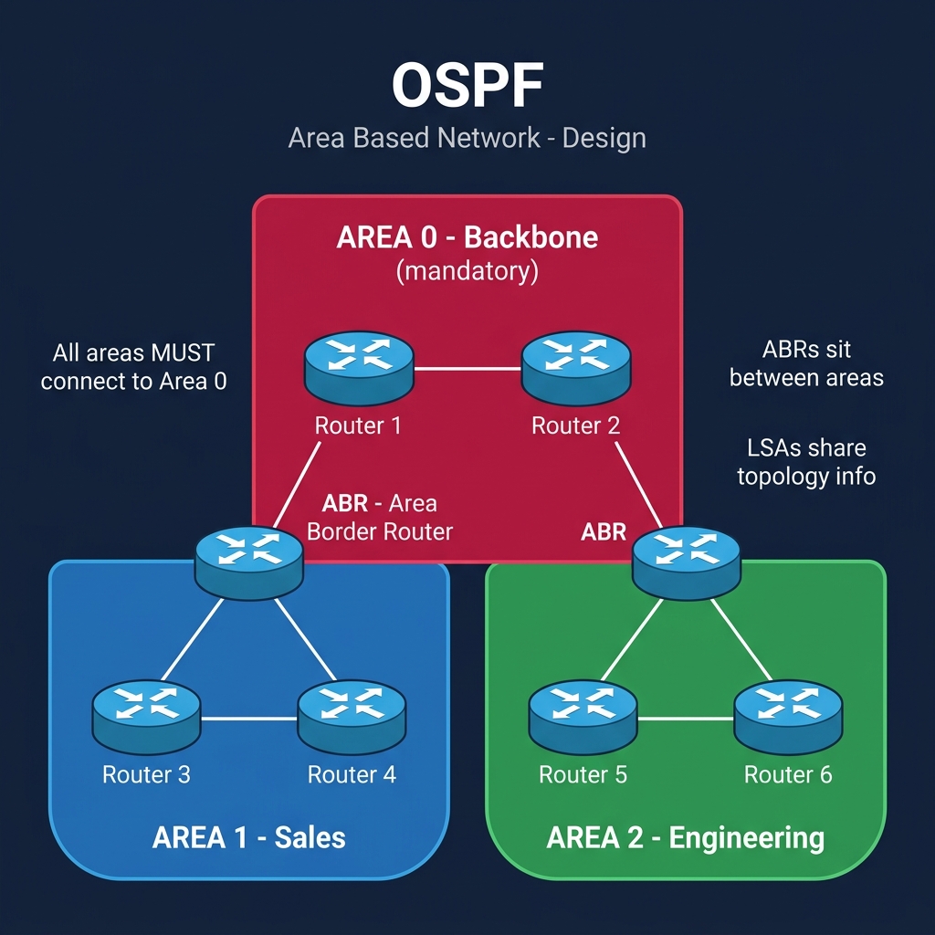
Key OSPF Rules:
- All areas MUST connect to Area 0 (backbone)
- ABRs (Area Border Routers) sit between areas
- LSAs (Link-State Advertisements) share topology information
Basic OSPF Configuration:
| Step | Command | Purpose |
|---|---|---|
| 1 | Router(config)# router ospf 1 |
Enable OSPF with process ID 1 |
| 2 | Router(config-router)# network 10.0.0.0 0.255.255.255 area 0 |
Advertise in backbone area |
| 3 | Router(config-router)# network 192.168.1.0 0.0.0.255 area 1 |
Advertise in area 1 |
BGP (Border Gateway Protocol)
| Attribute | Details |
|---|---|
| Type | Path-vector |
| Standard | Open (RFC 4271) |
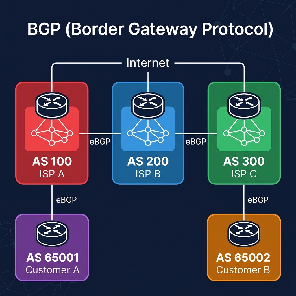
| Use Case | Internet-scale routing between Autonomous Systems (AS) |
| Metric | AS path length + multiple attributes (weight, local-pref, MED, etc.) |
| Admin Distance | 20 (eBGP), 200 (iBGP) |
| Transport | TCP port 179 |
| Scale | Handles 900,000+ routes (full internet routing table) |
BGP Autonomous System Peering:
Routing Protocol Comparison
| Feature | EIGRP | OSPF | BGP |
|---|---|---|---|
| Type | Hybrid | Link-state | Path-vector |
| Standard | Cisco (semi-open) | Open | Open |
| Scope | Interior (IGP) | Interior (IGP) | Exterior (EGP) |
| Algorithm | DUAL | Dijkstra SPF | Best-path selection |
| Metric | Bandwidth + Delay | Cost | AS path + attributes |
| Admin Distance | 90 | 110 | 20 (eBGP) / 200 (iBGP) |
| Scalability | Medium (single AS) | Large (area-based) | Internet-scale |
| Convergence | Very fast | Fast | Slow (by design — stability) |
Switching — VLANs & STP
VLANs (Virtual Local Area Networks)
A VLAN logically segments a physical switch into multiple isolated broadcast domains, without needing separate physical hardware.
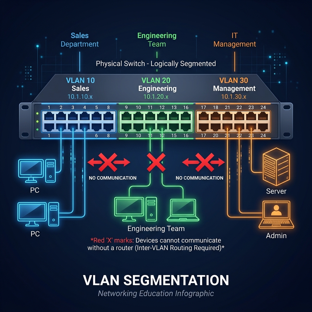
VLAN Benefits:
- Security — Isolate sensitive traffic (e.g., finance, management).
- Reduced broadcasts — Each VLAN is a separate broadcast domain.
- Flexibility — Group users logically regardless of physical location.
- Performance — Less broadcast overhead = more bandwidth for data.
VLAN Configuration:
| Step | Command | Purpose |
|---|---|---|
| 1 | Switch(config)# vlan 10 |
Create VLAN 10 |
| 2 | Switch(config-vlan)# name Sales |
Name the VLAN |
| 3 | Switch(config)# interface range fa0/1-8 |
Select port range |
| 4 | Switch(config-if-range)# switchport mode access |
Set ports as access ports |
| 5 | Switch(config-if-range)# switchport access vlan 10 |
Assign ports to VLAN 10 |
Trunk Port Configuration — carries traffic for multiple VLANs between switches using 802.1Q tagging:
| Step | Command | Purpose |
|---|---|---|
| 1 | Switch(config)# interface gi0/1 |
Select the uplink interface |
| 2 | Switch(config-if)# switchport mode trunk |
Set as trunk port |
| 3 | Switch(config-if)# switchport trunk allowed vlan 10,20,30 |
Allow specific VLANs |
STP (Spanning Tree Protocol — IEEE 802.1D)
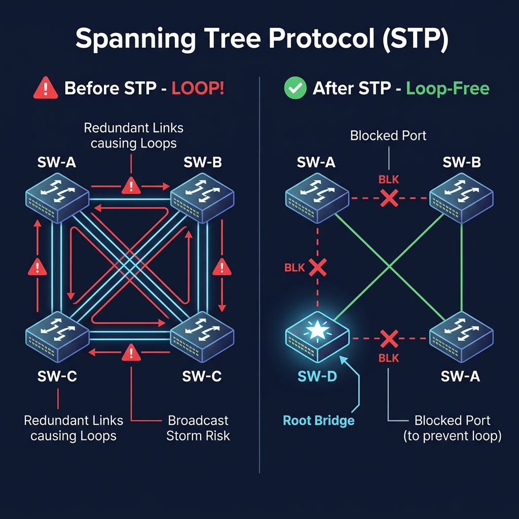
STP prevents Layer 2 loops (broadcast storms) by blocking redundant paths and maintaining a loop-free topology.
How STP Works:
- Root Bridge Election — The switch with the lowest Bridge ID (Priority + MAC) becomes the Root Bridge.
- Root Port Selection — Every non-root switch selects the port with the lowest cost path to the Root Bridge.
- Designated Port Selection — On each segment, the port with the best path to Root is the Designated Port.
- Blocking — All remaining redundant ports are placed into a Blocking state.
STP Port States:
| State | Duration | Receives Frames? | Sends Frames? | Learns MACs? |
|---|---|---|---|---|
| Blocking | — | (BPDUs only) | ||
| Listening | 15 sec | (BPDUs only) | (BPDUs) | |
| Learning | 15 sec | (BPDUs only) | (BPDUs) | |
| Forwarding | — | (all) | (all) | |
| Disabled | — |
Modern alternatives: RSTP (802.1w) converges in seconds instead of 30-50 seconds. PVST+ runs a separate STP instance per VLAN.
Quick Reference — Common Port Numbers
| Port | Protocol | Service |
|---|---|---|
| 20, 21 | TCP | FTP (Data / Control) |
| 22 | TCP | SSH |
| 23 | TCP | Telnet |
| 25 | TCP | SMTP |
| 53 | TCP/UDP | DNS |
| 67, 68 | UDP | DHCP (Server / Client) |
| 80 | TCP | HTTP |
| 110 | TCP | POP3 |
| 143 | TCP | IMAP |
| 443 | TCP | HTTPS |
| 3389 | TCP | RDP |
CLI Commands — CCNA Command Reference
A complete Cisco IOS command reference aligned to the CCNA 200-301 exam. Commands use angle brackets
< >for required parameters and square brackets[ ]for optional ones.
The IOS Mode Hierarchy
IOS uses nested command modes. You move deeper to configure and step back out to verify. The prompt always tells you where you are.
| Mode | Prompt | How to Enter | Purpose |
|---|---|---|---|
| User EXEC | Router> |
Default on login | Limited monitoring |
| Privileged EXEC | Router# |
enable |
Full monitoring, save, reload |
| Global Config | Router(config)# |
configure terminal |
Device-wide settings |
| Interface Config | Router(config-if)# |
interface <type> <num> |
Interface-specific settings |
| Line Config | Router(config-line)# |
line console 0 or line vty 0 4 |
Console / VTY access settings |
| Router Config | Router(config-router)# |
router ospf 1 etc. |
Routing protocol settings |
1. Device Access & Basic Commands
1.1 Navigation & Saving
| Command | Description |
|---|---|
enable |
Moves from User EXEC to Privileged EXEC mode |
disable |
Returns to User EXEC mode |
configure terminal |
Enters Global Configuration mode |
exit |
Steps back one mode level |
end |
Jumps directly back to Privileged EXEC mode |
copy running-config startup-config |
Saves the running config to NVRAM (survives reboot) |
reload |
Restarts the device. Unsaved changes are lost |
1.2 Show & Verification Commands
| Command | Description |
|---|---|
show running-config |
Displays the active (running) configuration |
show startup-config |
Displays the saved startup configuration |
show version |
IOS version, uptime, and hardware details |
show ip interface brief |
One-line IP and status summary per interface |
show ip route |
Displays the routing table |
show interfaces |
Detailed status and counters per interface |
show cdp neighbors |
Lists directly connected Cisco devices (CDP) |
show lldp neighbors |
Lists neighbors discovered via LLDP |
show clock |
Displays the device system time |
Tip: A line reading “administratively down” almost always means a missing
no shutdown. Filter long output withshow running-config | include ip route.
2. Device Security
2.1 Passwords & Users
| Command | Description |
|---|---|
enable secret <password> |
Sets the encrypted privileged-EXEC password |
service password-encryption |
Encrypts all plaintext passwords in the config |
username <user> secret <pass> |
Creates a local user with an encrypted password |
username <user> privilege <lvl> secret <pass> |
Creates a user with a defined privilege level |
login local |
Uses the local user database for line authentication |
2.2 Console & VTY Line Protection
| Command | Description |
|---|---|
line console 0 |
Enters console line configuration |
password <pass> / login |
Sets and enables a console password |
line vty 0 4 |
Enters configuration for VTY (remote) lines 0–4 |
banner motd #Text# |
Sets the message-of-the-day login banner |
2.3 SSH Hardening
| Command | Description |
|---|---|
ip domain-name <domain> |
Sets the domain name (required to generate RSA keys) |
crypto key generate rsa modulus 2048 |
Generates the RSA key pair used by SSH |
ip ssh version 2 |
Forces the more secure SSHv2 |
transport input ssh |
Restricts VTY access to SSH only |
no ip telnet server |
Disables the Telnet server |
Worked Example — Full SSH Lockdown:
| Step | Command | Notes |
|---|---|---|
| 1 | R1(config)# hostname R1 |
Set hostname (required for RSA) |
| 2 | R1(config)# ip domain-name example.com |
Set domain (required for RSA) |
| 3 | R1(config)# username admin privilege 15 secret S3cure! |
Create local admin user |
| 4 | R1(config)# enable secret Enable!23 |
Set enable password |
| 5 | R1(config)# service password-encryption |
Encrypt all passwords |
| 6 | R1(config)# crypto key generate rsa modulus 2048 |
Generate RSA keys |
| 7 | R1(config)# ip ssh version 2 |
Force SSHv2 |
| 8 | R1(config)# line vty 0 4 |
Enter VTY config |
| 9 | R1(config-line)# login local |
Use local user database |
| 10 | R1(config-line)# transport input ssh |
SSH only, no Telnet |
Watch Out: RSA key generation fails if no hostname or domain name is set. Always set both first. Never leave
transport input telneton a production device.
3. Interface Commands
| Command | Description |
|---|---|
interface <type> <number> |
Enters interface configuration mode |
ip address <ip> <mask> |
Assigns an IPv4 address to the interface |
ipv6 address <ipv6>/<prefix> |
Assigns an IPv6 address to the interface |
no shutdown |
Administratively enables (brings up) the interface |
shutdown |
Administratively disables the interface |
description <text> |
Adds a descriptive label to the interface |
speed <10|100|1000|auto> |
Sets the interface speed |
duplex <half|full|auto> |
Sets the duplex mode |
ip helper-address <ip> |
Forwards DHCP broadcasts to a server (DHCP relay) |
bandwidth <value> |
Sets reference bandwidth in kbps (routing metric) |
show interfaces <type number> |
Detailed status for a specific interface |
Worked Example — Configure a Routed Interface:
| Step | Command |
|---|---|
| 1 | R1(config)# interface gigabitEthernet 0/0 |
| 2 | R1(config-if)# description ## LINK TO R2 (WAN) ## |
| 3 | R1(config-if)# ip address 10.0.0.1 255.255.255.252 |
| 4 | R1(config-if)# no shutdown |
Watch Out: A speed or duplex mismatch is a classic Layer 1/2 fault. Leave both at
autounless you have a specific reason not to. Forgettingno shutdownleaves the interface administratively down.
4. Routing Commands
4.1 Static Routing
| Command | Description |
|---|---|
ip route <net> <mask> <next-hop> |
Adds a static route via a next-hop IP |
ip route <net> <mask> <exit-if> |
Adds a static route via an exit interface |
ip route 0.0.0.0 0.0.0.0 <next-hop> |
Adds a default (gateway-of-last-resort) route |
Example — R1 reach R3’s LAN via R2:
| Step | Command |
|---|---|
| 1 | R1(config)# ip route 172.16.20.0 255.255.255.0 10.0.0.2 |
| 2 | R1(config)# ip route 0.0.0.0 0.0.0.0 10.0.0.2 |
4.2 RIP
| Command | Description |
|---|---|
router rip |
Starts the RIP routing process |
version 2 |
Uses RIPv2 (classless, supports VLSM) |
network <net> |
Advertises a connected classful network into RIP |
no auto-summary |
Disables automatic summarisation (needed for VLSM) |
passive-interface <if> |
Stops RIP updates out of the named interface |
4.3 OSPF
| Command | Description |
|---|---|
router ospf <process-id> |
Starts an OSPF process (locally significant ID) |
router-id <ip> |
Manually sets the OSPF router ID |
network <net> <wildcard> area <id> |
Adds matching networks to an OSPF area |
area <id> range <net> <mask> |
Creates a summary (inter-area) route |
Example — Single-area OSPF on R1:
| Step | Command |
|---|---|
| 1 | R1(config)# router ospf 1 |
| 2 | R1(config-router)# router-id 1.1.1.1 |
| 3 | R1(config-router)# network 10.0.0.0 0.0.0.3 area 0 |
| 4 | R1(config-router)# network 172.16.10.0 0.0.0.255 area 0 |
4.4 Routing Verification
| Command | Description |
|---|---|
show ip route |
Displays the routing table |
show ip protocols |
Shows running routing protocols and their state |
show ip ospf neighbor |
Lists OSPF adjacencies and their state |
Note: The number in brackets like
[110/2]is[administrative distance / metric]. Lower AD wins: Connected 0, Static 1, EIGRP 90, OSPF 110, RIP 120.
5. Switching Commands (Layer 2)
5.1 VLANs
| Command | Description |
|---|---|
vlan <id> |
Creates a VLAN and enters VLAN config mode |
name <name> |
Assigns a name to the VLAN |
show vlan brief |
Summarises VLANs and their assigned ports |
interface range <range> |
Configures multiple interfaces at once |
5.2 Access & Trunk Ports
| Command | Description |
|---|---|
switchport mode access |
Forces the port into access mode |
switchport access vlan <id> |
Assigns the access port to a VLAN |
switchport mode trunk |
Forces the port into trunk mode |
switchport trunk allowed vlan <list> |
Restricts which VLANs cross the trunk |
switchport trunk native vlan <id> |
Sets the untagged (native) VLAN on the trunk |
switchport nonegotiate |
Disables DTP negotiation on the port |
Worked Example — VLANs and a Trunk:
| Step | Command | Notes |
|---|---|---|
| 1 | SW1(config)# vlan 10 |
Create VLAN 10 |
| 2 | SW1(config-vlan)# name SALES |
Name it |
| 3 | SW1(config-vlan)# vlan 20 |
Create VLAN 20 |
| 4 | SW1(config-vlan)# name ENG |
Name it |
| 5 | SW1(config)# interface range fa0/1 - 2 |
Select access ports |
| 6 | SW1(config-if-range)# switchport mode access |
Set as access |
| 7 | SW1(config-if-range)# switchport access vlan 10 |
Assign to VLAN 10 |
| 8 | SW1(config)# interface gig0/1 |
Select trunk port |
| 9 | SW1(config-if)# switchport mode trunk |
Set as trunk |
| 10 | SW1(config-if)# switchport trunk allowed vlan 10,20 |
Allow VLANs |
| 11 | SW1(config-if)# switchport trunk native vlan 99 |
Set native VLAN |
5.3 Spanning Tree & Verification
| Command | Description |
|---|---|
show interfaces trunk |
Lists trunk ports and allowed/native VLANs |
show mac address-table |
Displays the MAC address (CAM) table |
spanning-tree mode rapid-pvst |
Enables Rapid PVST+ spanning tree |
spanning-tree vlan <id> priority <val> |
Sets STP priority to influence root election |
Watch Out: The native VLAN must match on both ends of a trunk, or you will see a native-VLAN-mismatch error. STP priority must be a multiple of 4096.
6. Access Control Lists (ACLs)
ACLs filter traffic by matching addresses and ports. Rules are read top-down and the first match wins — every ACL ends with an invisible deny any.
| Command | Description |
|---|---|
access-list <n> permit <src> <wildcard> |
Adds a permit rule to a standard ACL |
access-list <n> deny <src> <wildcard> |
Adds a deny rule to an ACL |
access-list <n> permit any |
Permits all remaining traffic (usually placed last) |
ip access-group <n> in |
Applies the ACL inbound on an interface |
ip access-group <n> out |
Applies the ACL outbound on an interface |
show access-lists |
Displays ACLs and their hit counters |
Worked Example — Extended ACL (Allow HTTP, deny rest):
| Step | Command |
|---|---|
| 1 | R1(config)# access-list 100 permit tcp 192.168.1.0 0.0.0.255 any eq 80 |
| 2 | R1(config)# access-list 100 permit tcp 192.168.1.0 0.0.0.255 any eq 443 |
| 3 | R1(config)# access-list 100 deny ip any any |
| 4 | R1(config)# interface gig0/0 |
| 5 | R1(config-if)# ip access-group 100 in |
Note: Place standard ACLs close to the destination and extended ACLs close to the source. Standard ACL numbers: 1–99; Extended: 100–199.
7. NAT Commands
NAT maps private (inside) addresses to public (outside) addresses. PAT (NAT overload) lets many hosts share one public IP by tracking port numbers.
| Command | Description |
|---|---|
access-list <n> permit <inside-net> <wildcard> |
Defines the inside addresses to translate |
ip nat inside source list <n> interface <out> overload |
Configures PAT (NAT overload) |
ip nat inside |
Marks the interface as the inside (private) side |
ip nat outside |
Marks the interface as the outside (public) side |
show ip nat translations |
Displays the active translation table |
show ip nat statistics |
Displays NAT counters and statistics |
Worked Example — PAT to the Internet:
| Step | Command |
|---|---|
| 1 | R1(config)# access-list 1 permit 192.168.1.0 0.0.0.255 |
| 2 | R1(config)# ip nat inside source list 1 interface gig0/1 overload |
| 3 | R1(config)# interface gig0/0 |
| 4 | R1(config-if)# ip nat inside |
| 5 | R1(config)# interface gig0/1 |
| 6 | R1(config-if)# ip nat outside |
8. DHCP Commands
A router can act as a DHCP server, leasing addresses via the DORA exchange (Discover → Offer → Request → Acknowledge). Always exclude statically used addresses first.
| Command | Description |
|---|---|
ip dhcp excluded-address <start> <end> |
Reserves addresses the server must not lease |
ip dhcp pool <name> |
Creates a DHCP address pool |
network <net> <mask> |
Defines the subnet the pool serves |
default-router <ip> |
Sets the gateway handed to clients |
dns-server <ip> |
Sets the DNS server handed to clients |
lease <days> [hours] [minutes] |
Sets the address lease duration |
show ip dhcp binding |
Shows active lease bindings |
show ip dhcp pool |
Shows pool utilisation details |
Worked Example — DHCP Server for a LAN:
| Step | Command |
|---|---|
| 1 | R1(config)# ip dhcp excluded-address 192.168.1.1 192.168.1.10 |
| 2 | R1(config)# ip dhcp pool LAN_POOL |
| 3 | R1(dhcp-config)# network 192.168.1.0 255.255.255.0 |
| 4 | R1(dhcp-config)# default-router 192.168.1.1 |
| 5 | R1(dhcp-config)# dns-server 8.8.8.8 |
| 6 | R1(dhcp-config)# lease 7 |
Tip: If clients are on a different subnet than the server, add
ip helper-address <server-ip>on the client-side interface so broadcasts are relayed.
9. IPv6 Commands
IPv6 must be explicitly enabled for routing. Addressing uses a prefix length rather than a subnet mask.
| Command | Description |
|---|---|
ipv6 unicast-routing |
Globally enables IPv6 routing |
ipv6 address <ipv6>/<prefix> |
Assigns an IPv6 address to the interface |
ipv6 address <prefix>::/64 eui-64 |
Auto-generates the host portion from the MAC |
ipv6 route <net>/<prefix> <next-hop> |
Adds a static IPv6 route |
show ipv6 interface brief |
Summarises IPv6 interface addressing |
show ipv6 route |
Displays the IPv6 routing table |
Worked Example — IPv6 Addressing:
| Step | Command |
|---|---|
| 1 | R1(config)# ipv6 unicast-routing |
| 2 | R1(config)# interface gig0/0 |
| 3 | R1(config-if)# ipv6 address 2001:db8:acad:1::1/64 |
| 4 | R1(config-if)# ipv6 address fe80::1 link-local |
| 5 | R1(config-if)# no shutdown |
| 6 | R1(config)# ipv6 route ::/0 2001:db8:acad:1::2 |
Note: Every IPv6 interface automatically has a link-local address starting with
fe80::. The::/0route is the IPv6 default route, equivalent to0.0.0.0/0in IPv4.
10. Diagnostic & Troubleshooting Commands
| Command | Description |
|---|---|
ping <ip> |
Tests basic reachability to a host |
traceroute <ip> |
Traces the hop-by-hop path to a host |
show cdp neighbors detail |
Detailed CDP neighbor information |
debug ip <option> |
Starts real-time debugging output (CPU-intensive) |
undebug all |
Stops all active debugging |
clear ip route * |
Clears the routing table |
clear arp * |
Clears the ARP cache |
write memory |
Saves configuration (legacy save command) |
Ping output:
!= success,.= timeout,U= destination unreachable.Watch Out: Use
debugsparingly on production gear — it is CPU-intensive. Always follow withundebug all.
11. Line Commands
Line commands govern how administrators connect — over the console cable or remotely over the VTY lines.
| Command | Description |
|---|---|
line console 0 |
Enters console line configuration |
line vty 0 4 |
Enters VTY (remote) line configuration |
password <pass> |
Sets the line password |
login |
Requires login authentication on the line |
transport input telnet ssh |
Allows both Telnet and SSH access |
exec-timeout <min> <sec> |
Sets the idle session timeout |
logging synchronous |
Stops log messages breaking up typed commands |
Example — Protect the Console:
| Step | Command |
|---|---|
| 1 | R1(config)# line console 0 |
| 2 | R1(config-line)# password C0nsole! |
| 3 | R1(config-line)# login |
| 4 | R1(config-line)# exec-timeout 5 0 |
| 5 | R1(config-line)# logging synchronous |
12. Wildcard Mask Quick Reference
A wildcard mask is the inverse of a subnet mask: a 0 bit means “must match” and a 1 bit means “ignore”. They appear in ACLs and OSPF network statements.
| Subnet Mask | Wildcard Mask | CIDR / Class |
|---|---|---|
255.255.255.255 |
0.0.0.0 |
/32 (Host) |
255.255.255.252 |
0.0.0.3 |
/30 (Point-to-point) |
255.255.255.224 |
0.0.0.31 |
/27 |
255.255.255.192 |
0.0.0.63 |
/26 |
255.255.255.128 |
0.0.0.127 |
/25 |
255.255.255.0 |
0.0.0.255 |
/24 (Class C) |
255.255.0.0 |
0.0.255.255 |
/16 (Class B) |
255.0.0.0 |
0.255.255.255 |
/8 (Class A) |
How to Read a Command:
ip route 192.168.1.0 255.255.255.0 10.0.0.1
192.168.1.0— the destination network255.255.255.0— the network mask10.0.0.1— the next-hop address
13. Notes & Exam Tips
- Commands are not case-sensitive, but argument values (names, passwords) are.
< >= required parameter,[ ]= optional parameter.- The
?key shows context help; Tab completes a partial command. - Use
show ?to discover every verification command in your current mode. - Save early, save often:
copy running-config startup-config(orwrite memory). - Administrative Distance breaks routing ties: Connected 0, Static 1, EIGRP 90, OSPF 110, RIP 120.
- Well-known ports to memorize: 22 SSH, 23 Telnet, 53 DNS, 80 HTTP, 443 HTTPS, 67/68 DHCP.
Top 50 CCNA Interview Questions (Answered)
Networking Fundamentals
Q1. What is a computer network?
A computer network is a group of two or more interconnected devices (computers, servers, printers, phones) that can share data, resources, and services. Networks are classified by size: LAN (local), WAN (wide-area), MAN (metropolitan), and PAN (personal).
Q2. What is the difference between a LAN and a WAN?
Feature LAN WAN Scope Single building / campus Across cities, countries, or continents Speed High (1–100 Gbps) Lower (varies by link type) Ownership Privately owned Often uses ISP / telecom infrastructure Latency Very low Higher and variable Example Office network The internet, MPLS links between branches
Q3. What is a protocol?
A protocol is a set of standardized rules that govern how data is formatted, transmitted, and received over a network. Examples: TCP, IP, HTTP, OSPF, ARP. Without agreed-upon protocols, devices from different manufacturers could not communicate.
Q4. What is the difference between TCP and UDP?
Feature TCP UDP Connection Connection-oriented (3-way handshake) Connectionless Reliability Guaranteed delivery, ordering, error-checking Best-effort, no guarantee Speed Slower (overhead from acknowledgments) Faster (minimal overhead) Use Cases HTTP, FTP, SSH, email DNS, DHCP, VoIP, streaming, gaming Header Size 20 bytes minimum 8 bytes fixed
Q5. What is the purpose of the TCP three-way handshake?
It establishes a reliable connection between client and server before data transfer: SYN (client requests connection) → SYN-ACK (server acknowledges and responds) → ACK (client confirms). This ensures both sides are ready and agree on initial sequence numbers.
Q6. What is a MAC address?
A Media Access Control address is a unique 48-bit hardware identifier burned into every NIC (Network Interface Card). It is written in hexadecimal as six octets (e.g.,
AA:BB:CC:DD:EE:FF). MAC addresses operate at Layer 2 and are used for local frame delivery within a LAN.
Q7. What is the difference between a MAC address and an IP address?
Feature MAC Address IP Address Layer Layer 2 (Data Link) Layer 3 (Network) Length 48 bits (6 hex octets) 32 bits (IPv4) or 128 bits (IPv6) Assignment Burned-in by manufacturer Assigned by admin or DHCP Scope Local network (LAN) only End-to-end across networks Changes? Permanent (can be spoofed) Can change (DHCP lease, reassignment)
Q8. What is ARP and how does it work?
Address Resolution Protocol maps a known IP address to an unknown MAC address on a local network. The host broadcasts an ARP Request (“Who has 10.0.0.1?”). The device with that IP replies with a unicast ARP Reply containing its MAC. Results are cached in the ARP table to avoid repeated broadcasts.
Q9. What is a broadcast domain and a collision domain?
- Broadcast domain: The set of devices that receive a broadcast frame. A router (or VLAN) creates a boundary — broadcasts do not cross routers.
- Collision domain: The set of devices sharing the same physical medium where simultaneous transmissions can collide. Each switch port is its own collision domain; hubs share one.
Q10. What is the difference between half-duplex and full-duplex?
- Half-duplex: Data can flow in only one direction at a time (like a walkie-talkie). Used with hubs.
- Full-duplex: Data flows in both directions simultaneously (like a phone call). Used with switches. Full-duplex effectively doubles bandwidth and eliminates collisions.
OSI & TCP/IP Models
Q11. What are the 7 layers of the OSI model?
From bottom to top: Physical (bits) → Data Link (frames) → Network (packets) → Transport (segments) → Session → Presentation → Application (data). Mnemonic: “Please Do Not Throw Sausage Pizza Away.”
Q12. What is the difference between the OSI model and the TCP/IP model?
The OSI model has 7 layers and is a theoretical reference framework. The TCP/IP model has 4 layers (Network Access, Internet, Transport, Application) and is the practical model the internet actually runs on. TCP/IP merges OSI Layers 5–7 into one Application layer and Layers 1–2 into one Network Access layer.
Q13. At which OSI layer do routers operate?
Layer 3 (Network). Routers make forwarding decisions based on logical IP addresses and routing tables.
Q14. At which OSI layer do switches operate?
Layer 2 (Data Link). Switches forward frames based on MAC addresses using a CAM (MAC address) table. Layer 3 switches can also route between VLANs.
Q15. What is encapsulation?
Encapsulation is the process of wrapping data with protocol headers (and sometimes trailers) as it moves down the OSI/TCP-IP stack. At each layer, a new header is added: Data → Segment → Packet → Frame → Bits. The receiving host reverses this (de-encapsulation).
IP Addressing & Subnetting
Q16. What is an IP address?
An IP address is a logical 32-bit (IPv4) or 128-bit (IPv6) identifier assigned to a network interface. It has two parts: the network portion (identifies the subnet) and the host portion (identifies the device on that subnet). The subnet mask determines the boundary between the two.
Q17. What are the IPv4 address classes?
Class Range Default Mask Networks Hosts/Network A 1.0.0.0 – 126.255.255.255 /8 126 ~16.7 million B 128.0.0.0 – 191.255.255.255 /16 ~16,000 ~65,000 C 192.0.0.0 – 223.255.255.255 /24 ~2 million 254 D 224.0.0.0 – 239.255.255.255 — Multicast — E 240.0.0.0 – 255.255.255.255 — Experimental —
Q18. What is the difference between public and private IP addresses?
Private IPs are reserved for internal use and are not routable on the internet:
10.0.0.0/8,172.16.0.0/12,192.168.0.0/16. Public IPs are globally unique and routable on the internet. NAT translates between the two.
Q19. What is subnetting and why is it used?
Subnetting divides a large network into smaller, more manageable sub-networks by borrowing bits from the host portion of an address. Benefits: reduced broadcast traffic, improved security through isolation, more efficient use of IP address space, and easier troubleshooting.
Q20. What is CIDR notation?
Classless Inter-Domain Routing notation expresses an IP address and its subnet mask in one compact form:
192.168.1.0/24. The/24means the first 24 bits are the network portion. CIDR replaced classful addressing to allow more flexible allocation.
Q21. What is a default gateway?
The default gateway is the router interface on the local subnet that a host sends traffic to when the destination is on a different network. If no more specific route exists, the packet goes to the default gateway. It’s configured via DHCP or manually.
Q22. What is DHCP and how does it work?
Dynamic Host Configuration Protocol automatically assigns IP addresses and other parameters (mask, gateway, DNS) to clients using the DORA process: Discover (client broadcasts) → Offer (server offers an IP) → Request (client accepts) → Acknowledge (server confirms the lease).
Q23. What is DNS?
Domain Name System translates human-readable domain names (e.g.,
www.google.com) into IP addresses (e.g.,142.250.80.4). DNS uses a hierarchical system of servers: root servers → TLD servers (.com, .org) → authoritative servers. It primarily uses UDP port 53.
Routing
Q24. What is routing?
Routing is the process of selecting the best path for a packet to travel from source to destination across one or more networks. Routers maintain a routing table containing known networks and their associated next-hop addresses or exit interfaces.
Q25. What is the difference between static and dynamic routing?
Feature Static Routing Dynamic Routing Configuration Manually entered by admin Automatically learned via protocols Scalability Poor (doesn’t adapt) Good (adapts to topology changes) CPU/Bandwidth Minimal overhead Uses resources for protocol updates Best For Small networks, stub routes, default routes Medium to large networks Examples ip routecommandOSPF, EIGRP, BGP, RIP
Q26. What is Administrative Distance (AD)?
AD is a value (0–255) that indicates the trustworthiness of a routing source. When multiple routing protocols offer a route to the same destination, the route with the lowest AD is preferred. Key values: Connected 0, Static 1, EIGRP 90, OSPF 110, RIP 120.
Q27. What is OSPF?
Open Shortest Path First is a link-state Interior Gateway Protocol (IGP) that uses Dijkstra’s SPF algorithm to find the shortest path. It uses cost (based on bandwidth) as its metric, supports area-based hierarchy (Area 0 is mandatory), and converges quickly via Link-State Advertisements (LSAs). AD = 110.
Q28. What is the difference between OSPF and EIGRP?
Feature OSPF EIGRP Type Link-state Advanced distance-vector (hybrid) Standard Open (RFC 2328) Cisco-proprietary (partially open) Algorithm Dijkstra SPF DUAL Metric Cost (bandwidth) Composite (bandwidth + delay) AD 110 90 Hierarchy Area-based (Area 0 mandatory) Flat (single AS) Convergence Fast Very fast (feasible successors)
Q29. What is BGP and when is it used?
Border Gateway Protocol is the path-vector Exterior Gateway Protocol (EGP) that routes traffic between Autonomous Systems on the internet. It uses TCP port 179 and selects routes based on AS path length and policy attributes. BGP handles 900,000+ routes in the full internet routing table. AD: eBGP 20, iBGP 200.
Q30. What is a routing loop and how is it prevented?
A routing loop occurs when packets endlessly circulate between routers without reaching their destination. Prevention mechanisms include: split horizon (don’t advertise a route back on the interface it was learned from), route poisoning (advertising a failed route with infinite metric), hold-down timers, and TTL (Time to Live — decrements at each hop, packet dropped at 0).
Switching & VLANs
Q31. What is a switch and how does it work?
A switch is a Layer 2 device that forwards Ethernet frames based on MAC addresses. It builds a CAM table (MAC address table) by learning the source MAC from incoming frames. When a frame arrives, the switch checks the destination MAC: if it’s in the table, it forwards to that port; if not, it floods the frame to all ports (except the source).
Q32. What is a VLAN?
A Virtual Local Area Network logically segments a physical switch into multiple isolated broadcast domains without requiring separate hardware. Devices in the same VLAN can communicate directly; devices in different VLANs require a router (inter-VLAN routing) to communicate. VLANs improve security, reduce broadcasts, and increase flexibility.
Q33. What is a trunk port?
A trunk port carries traffic for multiple VLANs between switches (or between a switch and a router). It uses 802.1Q tagging to insert a VLAN ID into each frame so the receiving switch knows which VLAN the frame belongs to. The native VLAN is sent untagged.
Q34. What is the difference between an access port and a trunk port?
Feature Access Port Trunk Port VLANs Belongs to one VLAN only Carries multiple VLANs Tagging No VLAN tags Uses 802.1Q tagging Connected to End devices (PCs, printers) Other switches, routers Configuration switchport mode accessswitchport mode trunk
Q35. What is STP and why is it needed?
Spanning Tree Protocol (IEEE 802.1D) prevents Layer 2 loops (broadcast storms) in networks with redundant links. It works by electing a Root Bridge (lowest Bridge ID), then calculating the shortest path from every switch to the Root. Redundant ports are placed in Blocking state to ensure a loop-free topology. RSTP (802.1w) converges in seconds vs. STP’s 30–50 seconds.
Q36. What is inter-VLAN routing?
Inter-VLAN routing allows communication between different VLANs. Methods include: (1) Router-on-a-stick — a single router interface with sub-interfaces, each tagged for a VLAN, connected to a trunk port; (2) Layer 3 switch — uses SVIs (Switch Virtual Interfaces) to route between VLANs internally, which is faster and more scalable.
Network Security
Q37. What is a firewall?
A firewall is a security device (hardware or software) that monitors and filters network traffic based on predefined rules. It sits between trusted (internal) and untrusted (external/internet) networks. Firewalls can be stateless (filter individual packets by header) or stateful (track connection states for more intelligent filtering).
Q38. What is an ACL?
An Access Control List is a set of rules applied to a router interface to permit or deny traffic based on source/destination IP, protocol, and port numbers. Rules are evaluated top-down — first match wins, and there’s an implicit
deny anyat the end. Standard ACLs (1–99) filter by source IP only; Extended ACLs (100–199) filter by source, destination, protocol, and port.
Q39. What is a DMZ?
A Demilitarized Zone is an isolated sub-network between the internal network and the internet. It hosts public-facing services (web servers, email, DNS) while protecting the internal network. A dual-firewall DMZ uses an outer firewall facing the internet and an inner firewall protecting internal resources.
Q40. What is the difference between SSH and Telnet?
Both provide remote CLI access to network devices, but Telnet (port 23) transmits everything in plaintext — including passwords — making it insecure. SSH (port 22) encrypts the entire session. Always use SSH; Telnet should be disabled on production devices.
Q41. What is port security?
Port security is a Layer 2 feature on switches that restricts which MAC addresses can use a specific port. If an unauthorized MAC is detected, the port can shutdown, restrict (drop + log), or protect (drop silently). This prevents unauthorized devices from connecting and mitigates MAC flooding attacks.
NAT & Network Services
Q42. What is NAT and why is it used?
Network Address Translation translates private (inside) IP addresses to public (outside) IP addresses and vice versa. It’s used because IPv4 address space is exhausted — NAT allows thousands of internal hosts to share a small pool of (or a single) public IP. Types: Static NAT (1:1 mapping), Dynamic NAT (pool-based), PAT/NAT Overload (many:1 using port numbers).
Q43. What is PAT (Port Address Translation)?
PAT (also called NAT Overload) allows many internal hosts to share one public IP address by differentiating sessions using unique port numbers. For example, 192.168.1.10:1024 and 192.168.1.11:5000 both translate to 203.0.113.5 but with different source ports. PAT is the most common form of NAT used in home and enterprise networks.
Q44. What is the difference between NAT and PAT?
Feature NAT (Static/Dynamic) PAT (NAT Overload) Mapping 1:1 (one private to one public) Many:1 (many private to one public) Tracking By IP address only By IP + port number Public IPs needed One per internal host One for all hosts Use case Servers needing fixed public IPs General internet access
IPv6
Q45. Why was IPv6 created?
IPv4 uses 32-bit addresses, providing ~4.3 billion addresses — insufficient for the modern internet. IPv6 uses 128-bit addresses, providing approximately 3.4 x 10^38 addresses (virtually unlimited). IPv6 also eliminates NAT (end-to-end reachability), has built-in IPsec, simplified headers, and supports auto-configuration (SLAAC).
Q46. What is the format of an IPv6 address?
An IPv6 address is 128 bits written as 8 groups of 4 hexadecimal digits separated by colons:
2001:0db8:85a3:0000:0000:8a2e:0370:7334. Shortening rules: leading zeros in a group can be dropped (0db8→db8), and one consecutive run of all-zero groups can be replaced with::(e.g.,2001:db8::8a2e:370:7334).
Q47. What is the difference between link-local and global unicast IPv6 addresses?
Feature Link-Local Global Unicast Prefix fe80::/102000::/3Scope Single link/subnet only Globally routable (internet) Assignment Auto-generated on every interface Manually or via SLAAC/DHCPv6 Routing Not forwarded by routers Routed across networks Use Neighbor discovery, routing protocol next-hop Normal internet communication
Troubleshooting & General
Q48. What is the difference between ping and traceroute?
Ping tests basic reachability to a destination using ICMP Echo Request/Reply — it tells you if the destination is reachable and the round-trip time. Traceroute maps the entire hop-by-hop path to a destination by sending packets with incrementing TTL values. Each router that decrements TTL to 0 sends back a “Time Exceeded” message, revealing itself.
Q49. A user cannot access the internet. Walk through your troubleshooting approach.
Follow the OSI bottom-up approach:
- Layer 1 (Physical): Check cable, link lights,
show interfacesfor up/up status.- Layer 2 (Data Link): Check MAC table, VLAN assignment, trunk status.
- Layer 3 (Network): Verify IP address, subnet mask, default gateway. Ping the gateway. Check routing table (
show ip route). Verify NAT/ACLs.- Layer 4+ (Transport/App): Check DNS resolution, firewall rules, port numbers, application-specific config. At each step, ping to isolate where the failure occurs.
Q50. What is the difference between a router and a Layer 3 switch?
Feature Router Layer 3 Switch Primary Function Routes between networks (WAN + LAN) Routes between VLANs (LAN) Interfaces Serial, Ethernet, WAN links Many Ethernet ports Routing Speed Software-based (slower) Hardware-based / ASIC (very fast) WAN Support Yes (PPP, HDLC, Frame Relay) No (LAN only) Features NAT, VPN, full ACLs, QoS Inter-VLAN routing, basic ACLs Best For WAN edge, internet access, branch offices Campus core/distribution, inter-VLAN